|
|
|
|
|
|
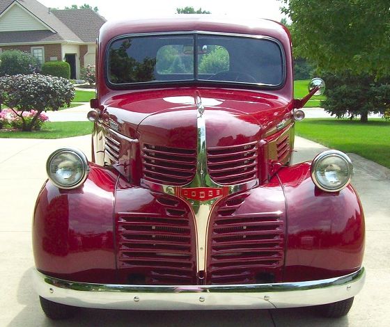 |
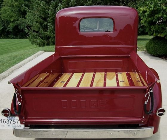
The story doesn't begin with this blog (click the Gift Booklet link for what happened first). This begins at the time I became aware of a rebuilt 1941 Dodge Pickup truck sitting in our driveway on August 9, 2014. Supposedly, our three sons came with their families to attend their mother's family reunion (which surprised me). But they had an ulterior motive (which really surprised me), a project they'd been working on for years. An awesome gift for Dad!

|
 |
|
|
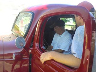
Here's how it looked that day. What a beauty! But whose truck was it? And what was it doing in our driveway?
|
|
|
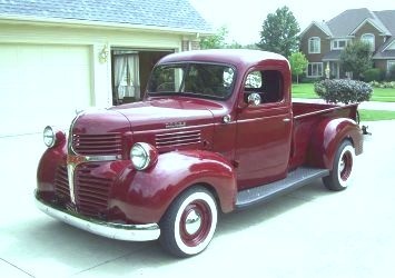
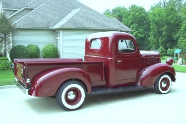
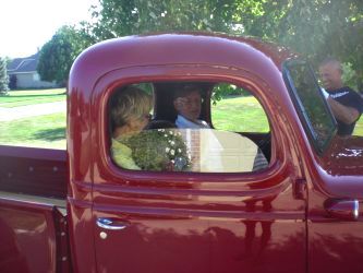
They told me, "Get in; it's yours." I was simply overwhelmed and couldn't quite comprehend it all ... but I got in.
 |
|
|
The boys apologized for not having everything quite finished (are you kidding?), but they had a shipping deadline
| |
|
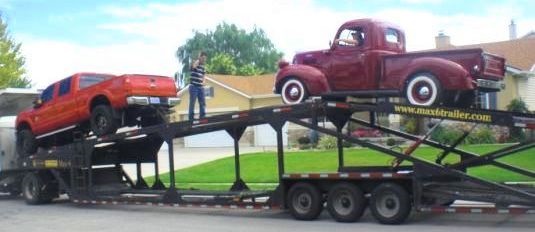 |
to meet and everything took longer than expected. The Dodge had been rebuilt in Utah and loaded on a transport just before our second son and his family flew to Fort Wayne. I didn't know it, but the Dodge arrived two days after they did. With the help of my wife, they located a neighbor's garage to park it in for a couple of days.

The evening before the truck appeared in our driveway, the brothers said they were going |
|
|
to have a night out together, so we stayed home with our three young granddaughters while they went out for dinner. I thought it was great that they were having fun together ... until one of them called about 11 PM and said they'd be later than expected. At that point I hoped they weren't having too much fun. Anyhow, we went to bed. Little did I know that all of them (spouses included) were in our friend's garage working on the truck until about 3 AM, getting it cleaned up and making final preparations to surprise me the next day.

|
|
|
Before the truck arrived in our driveway, the original flathead 3.3 liter I6 engine (below left) had been replaced with a 5.9 liter Magnum V8 (below right); the original 3-speed manual transmission had been replaced with a rebuilt Dodge 44RE 4-speed automatic, with power steering, power brakes, new drive shaft, wheels and shocks.
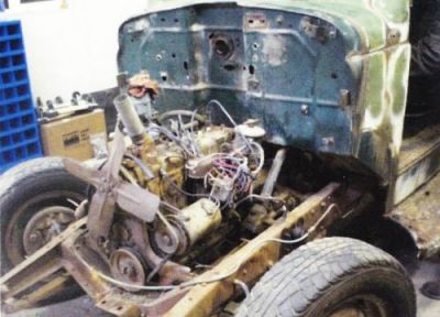
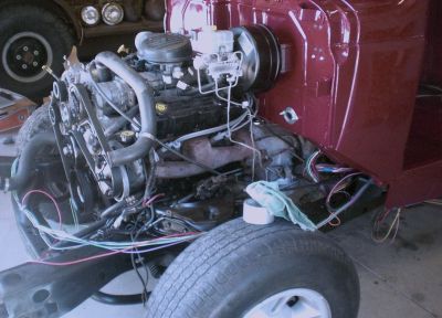
All of this was consistent with my wish to have the appearance of a 1941 pickup truck, but equipped with modern parts for better performance, handling, safety, and reliability. I got what I wanted. But looking at it, you had to wonder what wasn't done yet? Two things: finishing off the engine compartment and the interior of the cab.

That was perfect, because it provided a way for me to get involved in the completion of the project, albeit in a small way. After the families returned home, our oldest granddaughter from Connecticut stayed for a week, and when our oldest son returned to take her back home, he stayed for a few days and started the additional work. First thing on our agenda was a set of seat belts, an overflow tank for coolant, a thermostat to control the fan, and new aluminum valve covers. While he started work on the thermostat, I stuffed some old carpet padding in the springs of the bench seat and wedged 1/4" plywood below the old coils to reduce the bounce.

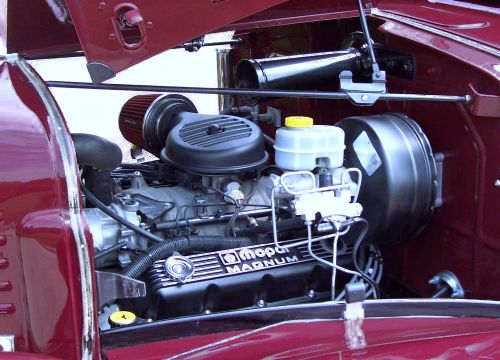
Installation of a 13" stainless steel vertical overflow tank and Mopar cast aluminum valve covers, along with some clean-up work, gave the engine compartment a whole new look (see below left and right, for before and after).
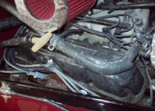
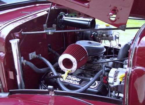
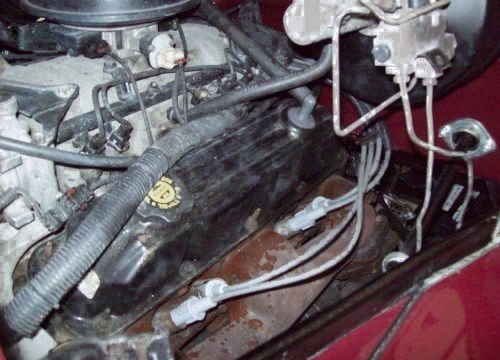

|
|
|
Everything under the hood went pretty much as planned, but the first attempt at seat belts didn't work out so well. We picked out two two-point retractable seat belts, but there was no room to mount the retractable units. So the retractable belts went back and three two-point lap belts were installed.

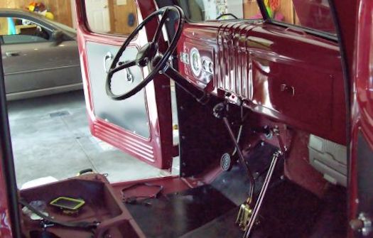
That was an improvement in the cab, but the belts didn't change the looks; they were installed for safety reasons. We still had a part-original/part-fabricated bare floor that needed to be covered and boots to install on the emergency brake and Lokar shifter. It was six months later before I got that done.

|
|
|
|
The first of September, my oldest son returned to do some more work they wanted to finish. This time it was to cut a hole in the floor and build a plate that could be removed to access the side-mounted battery which resided under the floorboard (under the driver's feet). While frequent battery access wasn't expected, there was no way to remove it without taking up the entire fabricated floor. Obviously a better solution was required, so a cut-out was made, pieces welded, a plate built and installed. We would preserve the access when the carpeting went in.
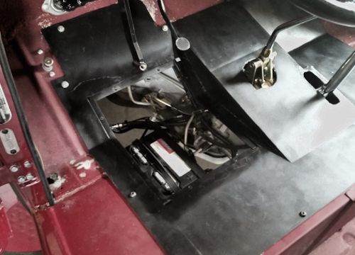
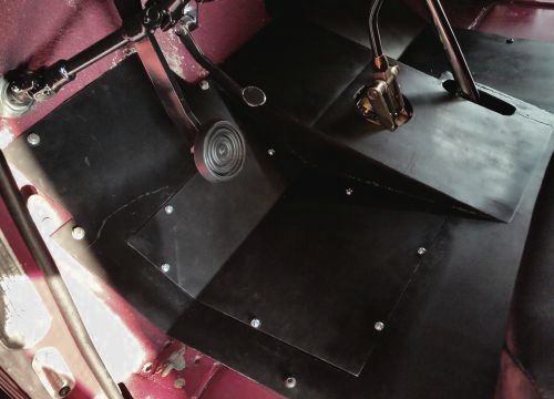
In addition to work on the floor, the speedometer got hooked up and calibrated. Things were coming together and I was learning a lot. Boys usually learn car stuff from their dad; but this dad was learning it from his boys.

With the plate installed, it was time to think about the carpeting. I recognized that the center ramp on the fabricated floor would present a problem. One couldn't just lay a piece of carpet in there; the distance up the ramp was less than the distance along the two sides. Besides, trying to cut and lay one large piece to size would be difficult with so many things to work around. So I decided to try a modular approach using some cheap 18" carpet tiles. This first attempt didn't look too bad (see below), but there were three issues to resolve: the unevenness of the floor, the adhesiveness of the material, and what to do with the firewall.
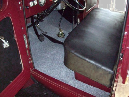
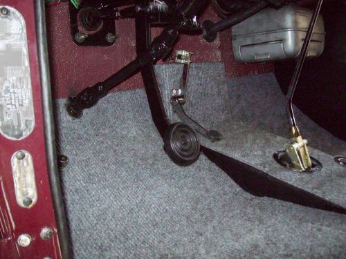

As with most carpeting, there needed to be some padding under it, but what to use that wouldn't slide around? A search led me to some Dynamat products that might do the trick, but with the colder weather coming, it didn't seem like a good time to be installing material that required heat. So I held off doing anything about the floor.

Good thing I did because my oldest son was back again in October to finish a couple more items: connecting a choke valve to the heater (to control flow), installing some new stainless steel headers, adjusting the exhaust pipes (as required) and wrapping them to the muffler to avoid unwanted heat. After squirting PB Blaster on the old exhaust headers every day for a week, the old rusty ones came off without busted bolts or knuckles. With only minor adjustments, the new custom headers (designed for a Dodge Durango) fit well. The heater choke valve installation went smoothly, providing one more hole in the firewall to put carpet around.

With the heater work done, things under the hood were mostly completed. I added a new fuel rail cap, four new dip sticks, and flex tubing on all the wiring to enhance the appearance. And with cold weather beginning to be more regular, the truck went up on jack stands for the winter.

Early in the spring of 2015, work resumed. I installed a new 330 Hz 12-volt horn because the original 6-volt horn didn't work, did some more dress-up work under the hood, got a steering wheel cover, and acquired The Club (steering wheel to brake pedal lock) for security. I had stalled long enough; it was time to do the carpeting.

|
|
|
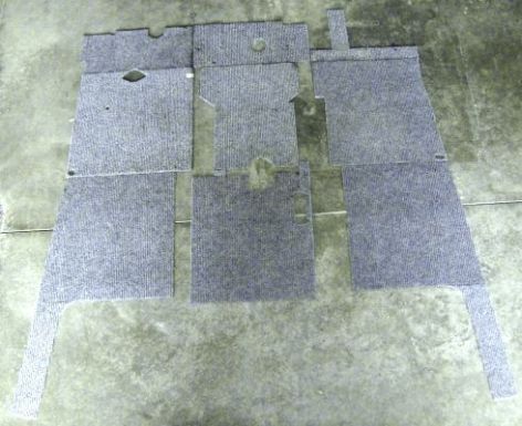
The first thing to do was to cut another set of carpet tile templates that would minimize the number of sections (and seams). The original set had started with the ramp, working both the left and right side. But the ramp wasn't in the center of the floor, so there was excess on the right, and the 18" tile on the left didn't reach the side of the cab. Thus, new templates were cut a few inches to the left for a better fit.

Having decided to cover the firewall, new templates were required for that, too. Laid out on the floor, the sections didn't look like they'd fit together, but that was because of the ramp and the inset center of the firewall. I decided to use black tiles with a hobnail pattern for the finished version to achieve a better edge blend, rather than the gray tiles with ridges. I couldn't find those tiles locally, but found them on line and ordered a box for final installation.

|
|
|
As I considered the boot installation, I recognized that there was no way to use the nuts and bolts that had come with the boot plates. Because of the fabricated floor, there was no way to put nuts on the bolts from the underside, and once the boots were on, there would be no way to do it from the top side either. So holes were drilled and then tapped to accommodate some new chrome-plated hex-head threaded bolts.

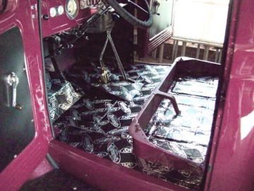
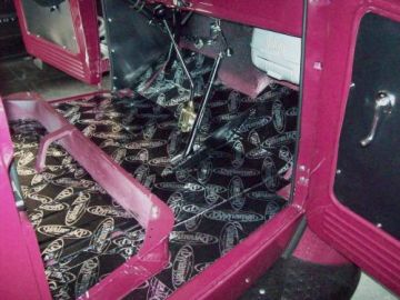
As noted above, I had determined that Dynamat products would provide a good adhesive base, serve as padding for carpet tiles, and provide both sound dampening and thermal protection. So, it became a three-step process: (1) Dynamat Xtreme, (2) Dynamat Dynaliner, and (3) carpet tiles. The first step put down two layers of 1/16" Xtreme on the original floor, the fabricated floor, and under the seat. One layer would have been sufficient for dampening, but two layers were needed to get the rise that would overcome screw heads on the battery access plate and the bolt heads of the original floor. Having extra material, I put Xtreme inside both doors, too.
|
|
|
The second step was installing 1/8-inch Dynamat Dynaliner on the fabricated floor, and 1/4-inch Dynaliner on the original floor. The two different heights evened up the floor (original to fabricated) for the carpet install. I also put 1/4-inch Dynaliner up on the driver and passenger sides of the firewall, and a 1/8-inch layer of Dynaliner on the center part of the firewall and wrapped it around the sides. Good adhesion; it stuck well to the firewall.
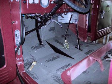
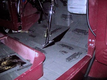
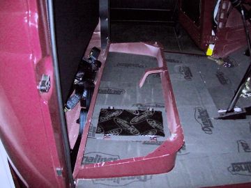
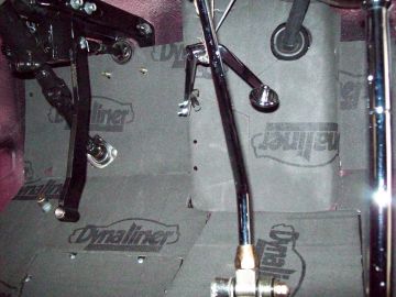
The final step was cutting the new black carpet tiles and putting them in place. As noted before, I switched from the gray ridged pattern tiles to a black hobnail design to better blend the edges of the tiles. Also, while installing the Dynaliner, I made sure that the seams in Dynaliner material would not match seams in the carpet tiles. Using the gray tiles as patterns, the new black carpet tile installation went well. After that, I used the original gray tile templates to fill the area under the seat. Here's how it looked with all of the carpet tiles installed.
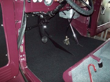
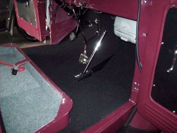
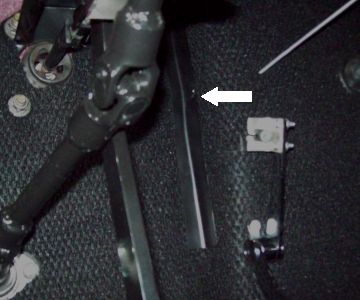
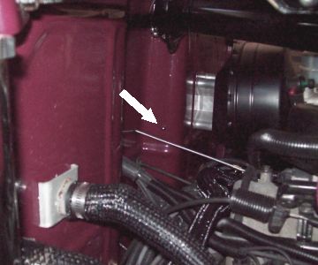
Because the carpet tiles were rather stiff, I was afraid the adhesion on the vertical tiles on the firewall might not hold (where the firewall curved around under the dash). The 18" width of the carpet tiles made joints necessary on both sides right at that location. So, I fabricated a brace for each side out of an old license plate to hold four carpet tiles in place on each side. Inside of the cab, the brace is not noticeable (see below left arrow). Under the hood, only one chrome acorn nut was required on each side (see below right arrow).
The next thing was to slip the boots on, trim the excess material, and set the chrome hex-head bolts for which threads had been tapped. Installing the boots was harder than I expected, but the job got done. I then laid in floor mats with Dodge logos over the black carpet for a final touch. Because the floor on the right side of the ramp was narrower than the floor on the left side, I had to trim quite a bit off the passenger side floor mat. It worked out okay, and here's how it ended up with boots and mats installed.
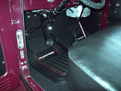
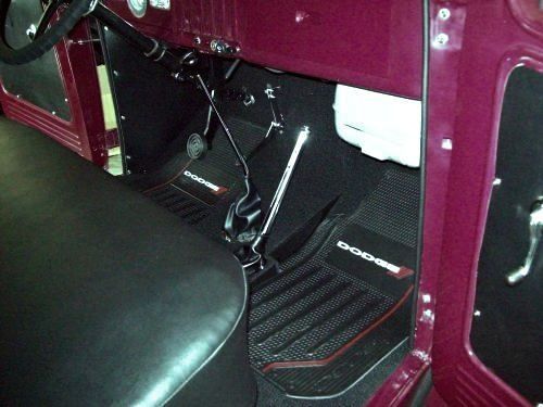

As of June, 2015, it was ready for a show ... so long as I didn't need to go very far or very fast. Driving the truck on the road at highway speeds revealed a vibration that had symptoms of a drive train problem. It wasn't engine rpm related, and I didn't feel it on the steering wheel, but I felt it on the Lokar shifter rod. So, when our oldest son visited again over the 4th of July, we tried to find the source. First thing to check: the working angles of the U-joints, but measurements showed the transmission and pinion angles to be within half a degree of each other. Horizontally, the engine, transmission, and differential were also aligned properly.

Examination of the U-joints showed them to be in good shape. The drive shaft was new (custom made) and had been balanced. The rear U-joint was disconnected to see if the transmission tail shaft was inserted far enough. It was, so we moved on to the differential. The cover was removed with minimal debris in the case or fluid. An inspection revealed no problems, so we scraped off the old gasket and applied a new gasket maker.

|
|
|
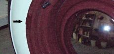
While waiting for the gasket maker to set, we took the rear wheels in to check for balance. It turned out they needed rebalancing, including the placement of weights on the outside of the rims (which had originally been avoided for the sake of appearance). We swallowed that pill and got them rebalanced to specs. Applying touch-up paint to the outside weights took care of the appearance and should inhibit rust on the steel weight (they aren't allowed to use lead weights anymore, you know).

|
|
|
|
So, what was the result of all this work? Not much. There was a bit of an improvement due to the rear wheel balancing, but there was still a serious vibration starting up around 45 mph and getting stronger at 55 mph and more. What's next to try? Rebalancing the front tires, replacing the U-joints, stabilizing the rear fenders, and rebalancing the drive shaft. With no steering wheel vibration, it's doubtful that rebalancing the front wheels will help, but it won't hurt. The U-joints are tight and do not heat up, but replacing them wouldn't hurt.

Stabilizing the rear fiberglass fenders may sound odd, but there's little else to try at the back end. Following the truck in a car told us that the back of both rear fenders oscillated vigorously at 45 mph or more (the left more than the right). But, is that causing the vibration? Or is that the result of the vibration? One wouldn't think that rear fender movement would cause a vibration to be felt in the drive train, but it's obvious that allowing the oscillation to continue would eventually take its toll on the fender fasteners.

So, to check out the effect of stablizing the fenders and better understand the dimensions, I built a temporary brace from the frame to the fender, using wood blocks, 3/8" dowels, and camper top padding (used on side rails of pickup truck beds). Photos below show the temporary support, which looks pretty ugly. The left photo is from under the fender looking in toward the frame; the right is from the frame looking out toward the fender.
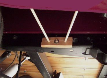
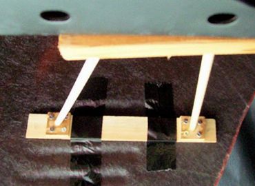

In the process, I discovered that the two fiberglass fenders were not the exact same shape. The bottom of the left rear fender bowed inward over an inch farther than the right rear fender. After the measurements revealed that, I noticed you could actually see the difference in the amount of tread visible on each tire when standing behind the truck. So, I decided to "push" out the left side using the same specs that applied to the right side. The result fully covered the tire tread visible from the rear on both sides.

Taking it out on the highway and getting it up to 70 mph was a pleasant surprise. The amount of vibration was significantly reduced, and there was no visible movement of the fenders following in a car. But slight vibration remained at 40 mph and recurred at 60 mph, but it faded below and above those speeds. So I had the front wheels rebalanced, allowing for outside weights. As noted earlier, the vibration wasn't noticeable on the steering wheel, but perhaps the redesign of the steering linkage (three U-joints to accommodate the original steering wheel location in the old '41 cab) was "camouflaging" the source.

No such luck. After rebalancing the front wheels, things remained pretty much the same. The vibrations were unchanged, but a test drive (with a following car) revealed another problem: intermittent brake light failure. The turn signals, tail lights, and emergency flashers all worked correctly and consistently on their own, but the brake lights only worked some of the time. So I digressed to find and fix the brake light problem.

Diagnosis led to the turn signal unit, an after-market box mounted on the steering column (the original '41 did not have turn signals, of course). For whatever reason, the contact locations in the turn signal box were "sloppy" in the "off" position and the turn signal lever had to be "wiggled just right" to make proper connection for the brake lights to work. So a new turn signal unit was ordered, wired and installed. Another problem solved.

In August 2015, our oldest son brought our oldest granddaughter out for a week's stay. He not only dropped off his daughter, but also a pair of welded fender braces matching the dimensions I'd provided. I merely added some of that "camper top" padding and replaced the temporary wooden ones with the permanent steel ones.
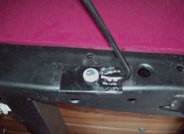
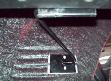
Getting back to the drive train vibrations issue, I decided it was time to go to a transmission shop for a professional opinion. That visit assured me the length of the drive shaft and insertion of the slip yoke was right; the only thing left was checking the balance of the driveshaft. My son in Utah said it was new and it had been balanced, but the wheels had also been balanced ... and they needed rebalancing. So I decided to pull out the driveshaft, remove the U-joints, and take the slip yoke and drive shaft in for new U-joints and rebalancing.

After getting the driveshaft back from the shop, I reinstalled it and drove around the neighborhood to make sure everything was working right. Back home, I added a little transmission fluid (lost some removing the driveshaft), then took it out on the highway. Guess what! It ran hard and fast without any prominent vibration at any speed. The new U-joints and rebalanced driveshaft (and everything else) did the trick. Task accomplished.

Before wrapping things up for the winter, I decided to get some major work done on the front end. It seemed the donor chassis had seen a lot of miles and rough use, so I had the upper and lower ball joints, sway bar end links, tie rods, and front wheel bearings replaced. The front end now has better stability, particularly going over those railroad tracks. However, getting that work done revealed two issues. Stripped threads in the right spindle of the brake caliper (repaired with a couple of Helicoils) and an inner fender making contact with the frame on the right side. So I got under there with a hack saw and vice grip pliers and cleared it from hitting the frame.

The first decent day in April, 2016, I got the trunk off the jack stands, checked the fluids and tires, installed the "loud" flasher my oldest son gave me for Christmas, (but I still can't hear over engine noise), cleaned things up a bit, and took it for a spin. Everything worked great and I'm set for more opportunities to show off "The Gift."

| |
|
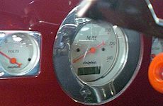
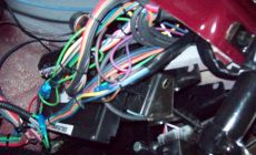
But then I noticed the cracked glass in the speedometer gauge. With the reflection in the photo at right, it may be hard to see the crack, but it was something that needed to be repaired. So I decided to pull it out, hoping I wouldn't screw up all the other gauges in the process. I didn't know how it was installed, so I had no idea how to get it out, and peering up under the dash (lower photo at right) showed me nothing but a maze of wiring so thick I couldn't get my hand up in there. Obviously, the speedometer was held in place with something from the back side, but I didn't know what held it up there ... and it was impossible to see whatever it was.

After a couple hours of working through the wires and feeling around, it was determined (with one finger) that there were a couple of clips and three screws. Unfortunately, the screws and bolts were more than "finger tight" so the next hurdle was to get a wrench in there to loosen them. Another couple of hours tried my patience, but persistence paid off and I had the speedometer loose from the dashboard. By turning it around and backing it into the hole, I was able to unplug the wiring harness from the speedometer case. Now it was free, but still hard to get out. After I did, I found there was no way to remove the glass. It had been fabricated as a single unit
|
 |
|
|
with the metal fame of the case bent around the edges of the glass to hold it in place. The only way to remove the glass was to "unbend" the metal casing that had been formed and pressed around the entire unit.

Once it was out, I found the glass to be fairly thick and housed in a rubber gasket within the metal casing. The next challenge, then, was to find a place to replace the glass. The original glass was convex, rather than flat, and the only place in town that could provide that was a custom-build stained-glass place. Since the cost of convex glass would be about the cost of a whole new set of gauges, I decided flat glass would look good. The reinstallation turned out be every bit as difficult as the removal, but the job is done ... and all the gauges work.

|
| |
|
|
|
|
|
|
But, just when you think you've worked out the kinks, another one shows it's ugly head. Actually, it was a noise in this case; a serious rattle that sounded like something was loose under the floor. From in the cab and on the road, it seemed to be associated with the emergency brake, so I looked for loose parts that could be causing it. Nothing was loose, so the next time my oldest son was here, I asked him to help me figure it out.

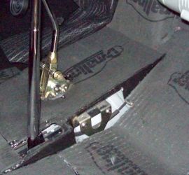
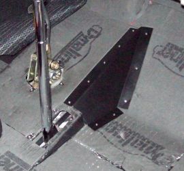
The only thing we could come up with was that two bolt heads that mounted the emergency brake cable on the transmission housing were resting on a vertical section of the fabricated floor. Nothing was loose, but when the frame flexed or transmission torque pulled the bolts away, they would come back and hit repeatedly causing the rattling noise. To confirm the theory, we used a ratchet strap to pull the tail of the transmission to the left side of the body frame, getting about a quarter-inch clearance between the mount and the vertical flooring.

|
|
|

|
A test drive with the strap in place confirmed our theory, but the strap wasn't a permanent fix. So what to do? We considered several ways to fix the problem, but the easiest seemed to be a modification of the floor so the emergency brake mount would be clear.

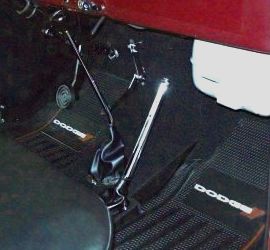
So, we pulled up the carpet, got out the Sawsall, and cut out the section of the floor that was causing the problem (see photo at right).

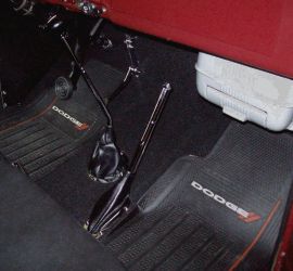
We replaced the original piece with a new angular piece, cut to provide adequate clearance (see lower photo at right).

The new piece was riveted in place (rather than screwed) to minimize carpet distortion. Dynamat Xtreme was applied to the top of the new piece as a sound and heat barrier, and the three pieces of removed carpet tiles were replaced to accommodate the new shape of the fabricated floor.
|


|
|
|
At this point I'm thinking all the work is done and I can simply enjoy the ride from here on ... but, as you know, there will always be something else to do with a project like this. As of this date, things have been working well. The truck has been out and about several times this summer, but I've decided car shows take too much time, so you may not see many more listed (unless it's a benefit, and the donation is for a worthy cause).

|
|
|
|
Shows Attended (click links below):

|
|
Last Blog Entry: 9/9/23 |
|
7/5/15 - Warren, IN
7/25/15 - Roanoke, IN
8/1/15 - Fort Wayne, IN
8/30/15 - Fort Wayne, IN
9/7/15 - Fort Wayne, IN
|
4/16/16 - Yoder, IN
8/6/16 - Fort Wayne, IN
9/25/16 - Fort Wayne, IN
7/29/17 - Fort Wayne, IN
10/1/17 - Fort Wayne, IN
|
9/23/18 - Fort Wayne, IN
9/9/23 - Fort Wayne, IN
|
|
|
|
|